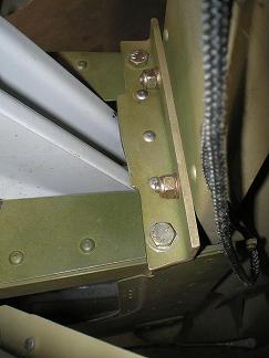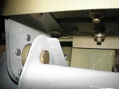

Attaching the EmpennageHorizontal Stab
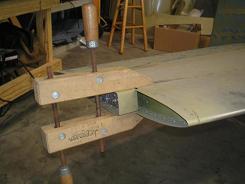
I found an easy way to check that the horizontal stab was level front to back was to insert a drill bit into each tooling hole. Make sure you use bits that just barely fit, so they stick straight out on their own. Then I placed the level on them.
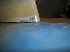
I countersunk from the top and bottom of the F-877, and bucked an AN426–5 rivet until the shop head filled the lower countersink. If you have to do this, don’t worry if you use too large a rivet. Once the countersink is filled, stop bucking, and get the grinder out. Grind and sand the leftover rivet until it is smooth. This leaves both the top and bottom of the F-877 smooth and the erroneous hole filled in. Then I clamped the horizontal stab back on, and inserted temporary bolts in all the other holes. This time when I drilled, the hole was true. I still don’t know how it happened. Vertical StabThe next step in attaching the empennage is the fitting of the vertical stabilizer. Locating the new match drilled vertical stab is a lot easier than the older one. I had to figure out the actual height of the vertical stab that is now determined by the predrilled hole that goes into the F-812B angle. I started at the bottom of the vertical stab by setting the VS-803 main spar to a height that would allow the bottom two bolts in the VS-410 to go through the WD-409 with enough edge distance. If you have the match drilled tail, make sure the marks you make to drill the three holes in “View A-A”, DWG 73 will have the required edge distance when drilled through the WD-409.
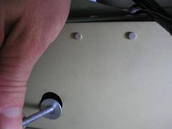
To continue with the empennage, it's time to attach the elevators. Once you determine the required washers or spacers for the elevator horns, make a little drawing. Set the washers and the drawing aside together. It may be a while before you finally install the elevators, and you don’t want to have to spend the time to figure the required spacers again. When you are drilling the F-841 pushrod hole in the elevator horns, make sure you use some sort of guide block. I used a hardwood block just like the directions, but I have seen others use a metal guide. The material you use isn’t that important, but the fact that you use something is. There is too much play between the horns if you don’t. If the holes in both horns don’t match, your elevators will not be even, and the plane won’t fly straight. Two parts left to the empennage: the elevator and rudder. The plans have you make and fit all the control pushrods for the elevators at this time. Don’t final install them however. Just fit them and then remove them. You will want access to the inside of the tail while installing wiring and other components, and when riveting the top skin. Then you can go back and final install the control system.
The front stop was easy to adjust. I had not yet riveted it in place, so I removed it, filed some metal off, reinstalled and checked it. I tried to file the rear stops with the elevators still installed, but there just wasn’t room. That meant I had to file a little off the stop, then reinstall the elevator and check.
If you have already installed the fiberglass tips, now is a good time to balance the elevators. Disconnect the pushrod from the elevator horns so each elevator floats free. Spray some WD-40 or LPS on the hinges, so they move easily. Now you have a perfect horizontal platform for balancing the elevators. I plan on test flying my RV-8 before painting, so I left them a little front heavy until after I finish painting. Then they will have to be balanced again. Finish the empennage attachment and fitting by adding the rudder stops. Take it slow and remove a little metal at a time. Remember that you can always take more off, but you can’t put it back. 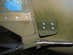 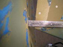 A few more Vertical Stabilizer attachment photos 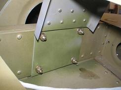 Forward vertical stabilizer bolts 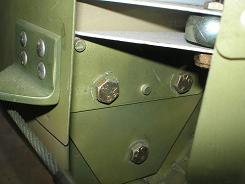 Lower aft vertical stabilizer bolts 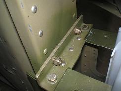 Vertical stabilizer rear attachment Return from Attaching the Empennage to Fuselage Return from Attaching the Empennage to Kit Plane Advice Home |
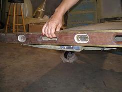 You
start by
leveling the
horizontal stab.
 In
my empennage
attachment process, I only had trouble at one spot on the
horizontal stab.
 Then
I
adjusted the front
of the
vertical stab and F-681
(now the F-884) attachment plate until they were in the proper position.
 I
wanted to ensure I had
the F-635
bellcrank in the neutral
position to adjust the lengths of the pushrods.