Substructure Assemblies
You will start building the fuselage by putting
together several substructure assemblies, later you will put
the assemblies together to complete the bottom ¾ of the fuselage.
Let’s get started!
There are several
sections in this article, so here's a quick list to get
you down to a particular one if you want that:
Firewall
Working
with stainless steel is a little different than working with
aluminum. It seems the edges get a lot sharper and will cut
you a lot easier than aluminum. Spend some time right at the
beginning dressing the edges so you don’t get cut while doing the rest
of the work.
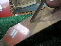 As
your drill bits get dull, they will
leave larger burrs on the backside of the stainless steel you are
drilling through. The easiest way I have found to remove
larger burrs is to use the flat end of a file like a chisel.
Place the file end against the burr and give it a smack with a
hammer. It will cleanly break off the burr. Then
you
can follow up with a deburring tool, scotchbrite wheel or emery cloth. As
your drill bits get dull, they will
leave larger burrs on the backside of the stainless steel you are
drilling through. The easiest way I have found to remove
larger burrs is to use the flat end of a file like a chisel.
Place the file end against the burr and give it a smack with a
hammer. It will cleanly break off the burr. Then
you
can follow up with a deburring tool, scotchbrite wheel or emery cloth.
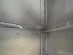 If
you are going to install the ground adjustable rudder pedals, there are
two rivets that need to be changed from the plan. OP-3, the
ground adjustable rudder pedal plans, show that each rivet just inboard
of
the F-801H on both sides needs to be an AN426AD4-5 with the flush head
on the inside of the fuselage instead of the AN470AD4-6 rivet shown in
the callout. This allows the rudder pedal attachment angle to
sit flush on the floor. It is a lot easier to countersink
now. These rivets will be installed when you rivet on the
bottom skin. Make a note in the RV-8 FORWARD FUSELAGE
SUBSTRUCTURE section of your plans on the step that reads
“Rivet the
(AN470 rivet locations only) Firewall Assembly to the Fwd Floor
Assembly…” I had to drill mine out when I got to the rudder pedals. If
you are going to install the ground adjustable rudder pedals, there are
two rivets that need to be changed from the plan. OP-3, the
ground adjustable rudder pedal plans, show that each rivet just inboard
of
the F-801H on both sides needs to be an AN426AD4-5 with the flush head
on the inside of the fuselage instead of the AN470AD4-6 rivet shown in
the callout. This allows the rudder pedal attachment angle to
sit flush on the floor. It is a lot easier to countersink
now. These rivets will be installed when you rivet on the
bottom skin. Make a note in the RV-8 FORWARD FUSELAGE
SUBSTRUCTURE section of your plans on the step that reads
“Rivet the
(AN470 rivet locations only) Firewall Assembly to the Fwd Floor
Assembly…” I had to drill mine out when I got to the rudder pedals.
Landing
Gear Box
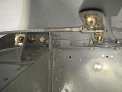 If
you are going to install
the ground
adjustable rudder pedals, this substructure is another spot where you
need to swap
out two rivets. The inboard rivets on each F-802G need
AN-426AD4-7 rivets with the flush head inside the fuselage instead of
the AN470AD4-7 rivets called for in the main plans. If you
are building the quickbuild, you can use a CS4-4 here. These rivets
will be installed when you rivet on the bottom skin. Make a
note in the RV-8
FORWARD BOTTOM SKINS section of your plans on the step
that reads “Rivet the F-802K-1 L.G. Forward Crossmember to the F-822-1
Forward Floor (DWG 61)…” If
you are going to install
the ground
adjustable rudder pedals, this substructure is another spot where you
need to swap
out two rivets. The inboard rivets on each F-802G need
AN-426AD4-7 rivets with the flush head inside the fuselage instead of
the AN470AD4-7 rivets called for in the main plans. If you
are building the quickbuild, you can use a CS4-4 here. These rivets
will be installed when you rivet on the bottom skin. Make a
note in the RV-8
FORWARD BOTTOM SKINS section of your plans on the step
that reads “Rivet the F-802K-1 L.G. Forward Crossmember to the F-822-1
Forward Floor (DWG 61)…”
Before your rivet all the
parts together, drill any holes you may need in the gearbox.
I had to drill holes for the fuel lines and electric wires in the
F-802-As and Bs. The new “-1” parts may already have these
holes drilled for you. See My
Wire Routing for pictures.
Forward
Fuselage Substructure
I have seen
several builders
make a large access panel in the F-866A Fwd Baggage Bulkhead, giving
them easy access to the back of the instrument panel. I
didn’t do this, but after spending a few hours on my back installing
the electrical system, I think next time I have to pull the panel, I
will make this access panel.
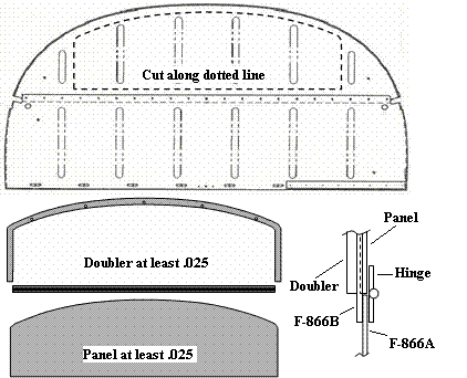
If
you are going to install an access panel,
do it now while you can work flat on the bench. If you cut
carefully, you can reuse the piece you removed as the panel
itself. If it gets messed up, or won’t hold it’s shape, get a
new piece of aluminum that is thick enough to hold it’s shape—as long
as it is at least the thickness of the original F-866A
(.025). You will also need a doubler (at least .025) around
the top of the hole you made—the hinge and lap joint with the F-866B
will be strong enough for the bottom. Make it straddle the
hole so you can rivet it to the F-866A and have the access panel screw
to it. Use a long piano hinge across the bottom and five
screws over the top.
Seat
Rib Assembly
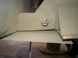 In
the older kit, we had to shape the ends of the
F-806C&D. If this is still the case, round the
corners only. Wait for filing of the bottoms until the wings
are fitted, and the rear attachment hole is marked. The
measurements there are critical, and if you have removed too much
metal, you may be in trouble. This is one of the only big
warnings in the plans, but it isn’t mentioned until you are fitting the
wings. In
the older kit, we had to shape the ends of the
F-806C&D. If this is still the case, round the
corners only. Wait for filing of the bottoms until the wings
are fitted, and the rear attachment hole is marked. The
measurements there are critical, and if you have removed too much
metal, you may be in trouble. This is one of the only big
warnings in the plans, but it isn’t mentioned until you are fitting the
wings.
Don’t forget to fit the trim and autopilot
brackets before riveting the substructure assembly together.
If you fit
them now, you will be able to use real rivets to hold them instead of
blind rivets if they are installed after the fuselage is built.
Make
sure you bend the edge of the skins before you dimple. See Skin
Lap Joints.
Longeron
Bending
My
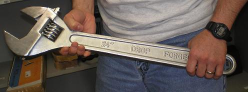
secret tool for twisting the longerons was a huge crescent
wrench. Don’t ask where I got it, because I don’t remember,
but it is a 24 inch crescent wrench. I set the jaws just
wide enough to slip onto the longeron, and used it to provide enough
leverage to twist the longeron and the smooth jaws didn’t mark up the
softer aluminum. By placing the longeron in the vice at the
spot where the bend started, and putting the wrench at the other end of
where the twist stopped, I got a nice, gradual twist in the part.
The
distances and degrees marked on the plans are not always easy to
measure. Bend them as close to the measurements as you
can—you will get a final fit by comparing them to the parts they will
match up to during the Forward Fuselage Substructure section.
Check that
you have opened the 90° angle the needed amount by using
the weldments that the forward ends of the longerons will fit
over. Once they fit nicely to both weldment webs without any
gaps, the angles are good.
Forward
Fuselage Section
I didn’t want to get
bend lines in
my curved F-804H-L&R, so I bent them over my knee. It
worked just fine as they aren’t that thick. But I couldn’t
bend the F-848 gussets that way, I had to bend them against the edge of
the bench. I made sure to use the curved wooden edge of the
bench to bend against. At least it minimized the angles in
the curve.
Make sure to mark the four F-8456 gussets
not only with the part number, but also with their orientation when
clecoed into the substructure. They look a lot alike, and can
be
easily reversed, swapped or installed upside down. My marks
washed off during priming, and I had a hard time getting them all back
in the right place.
After you have clecoed the F-804
Center Section Assembly to the Forward Fuselage Substructure, you will
install the F-843-L&R lower longerons. This is the
time that I mentioned earlier where you can ensure they fit
properly. You will have to cleco and clamp, check for fit,
then remove
and re-bend the longeron. Then start over again clecoing and
clamping. This is a slow process, but it is important to have
the parts fit correctly. Any space between the longeron and
another part will either pull the thinner part out of shape, leave
space between parts causing the structure to be weak, or put stress on
a part possibly causing it to fail.
Mid
Fuselage
Skins and Substructure
Bending the roll
in
the F-823
skins is accomplished very similarly to the way you rolled the leading
edges of the control surfaces. (See Bending
Leading Edges)
Make sure as you bend and roll that you keep some downward pressure to
prevent a crease. This is another spot where you have to
bend, fit, re-clamp and bend again. I did most of the bending
on the bench, and finished the last little bit by hand. I had
one spot that just didn’t want to lay flat, so a little persuasion with
a rubber mallet was called for. When I was ready to drill and
rivet, I used a large strap clamp all the way around the fuselage to
hold the curved sections tight to the bulkheads.
Finishing
Initial Assembly
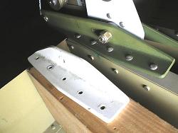 A
quick note on the
F-635 bellcrank
substructure assembly. Before making, drilling and riveting
the attachment
brackets, decide on your autopilot. I built and installed,
then had to drill out and remove the original mounts to allow for the
larger mounts needed for my autopilot. If you haven’t decided
yet, wait on these parts until after you do. A
quick note on the
F-635 bellcrank
substructure assembly. Before making, drilling and riveting
the attachment
brackets, decide on your autopilot. I built and installed,
then had to drill out and remove the original mounts to allow for the
larger mounts needed for my autopilot. If you haven’t decided
yet, wait on these parts until after you do.
The
next several sections walk you through assembling the aft bulkheads,
ribs and longerons. Then you finally cleco all the parts
together, and the “Canoe” as my wife called it finally starts taking
shape. It’s now time to work
on the skins.
Return
from Substructure
Assemblies to Fuselage
Return from Substructure Assemblies
to Kit Plane Advice Home
|


 As
your drill bits get dull, they will
leave larger burrs on the backside of the stainless steel you are
drilling through. The easiest way I have found to remove
larger burrs is to use the flat end of a file like a chisel.
Place the file end against the burr and give it a smack with a
hammer. It will cleanly break off the burr. Then
you
can follow up with a deburring tool, scotchbrite wheel or emery cloth.
  If
you are going to install the ground adjustable rudder pedals, there are
two rivets that need to be changed from the plan. OP-3, the
ground adjustable rudder pedal plans, show that each rivet just inboard
of
the F-801H on both sides needs to be an AN426AD4-5 with the flush head
on the inside of the fuselage instead of the AN470AD4-6 rivet shown in
the callout. This allows the rudder pedal attachment angle to
sit flush on the floor. It is a lot easier to countersink
now. These rivets will be installed when you rivet on the
bottom skin. Make a note in the
  If
you are going to install
the ground
adjustable rudder pedals, this substructure is another spot where you
need to swap
out two rivets. The inboard rivets on each F-802G need
AN-426AD4-7 rivets with the flush head inside the fuselage instead of
the AN470AD4-7 rivets called for in the main plans. If you
are building the quickbuild, you can use a CS4-4 here. These rivets
will be installed when you rivet on the bottom skin. Make a
note in the
  In
the older kit, we had to shape the ends of the
F-806C&D. If this is still the case, round the
corners only. Wait for filing of the bottoms until the wings
are fitted, and the rear attachment hole is marked. The
measurements there are critical, and if you have removed too much
metal, you may be in trouble. This is one of the only big
warnings in the plans, but it isn’t mentioned until you are fitting the
wings.
 A
quick note on the
F-635 bellcrank
substructure assembly. Before making, drilling and riveting
the attachment
brackets, decide on your autopilot. I built and installed,
then had to drill out and remove the original mounts to allow for the
larger mounts needed for my autopilot. If you haven’t decided
yet, wait on these parts until after you do.