

Pitot Static SystemI
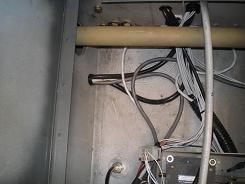
used neoprene tube,
connectors and rubber grommets for all of my pitot static system. I ran
the tube from the back of the
instruments, down the left gear box, under the floor, and out the left
wing or
into the tail. Either
conduit or rubber
grommets protect the tube as it passes through bulkheads. Having seen old plastic
lines become brittle and crumble, I opted for neoprene.
Pushing on the connectors is a lot easier
too.
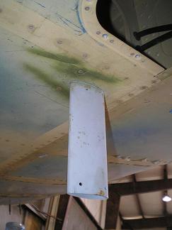
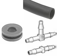 Pitot
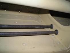 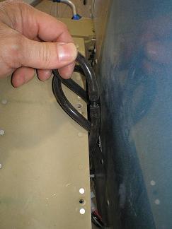 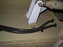 
Static I ran the static line back on the left side of the fuselage into the tail, and used a T connector to hook the tube to both static ports. I made the ports by drilling holes through the fuselage skin just below the F-887 upper longerons. I then pulled a large blind rivet (not a cherrymax) from the outside, and drilled the center pin out. The neoprene hose fit tight around the “shop head” of the rivet, but I also used two-part epoxy to glue it in place. I made use of the bracket from the remote compass to secure the tube by the static ports. A couple of zip ties hold the lines secure and take the weight off the connection with the rivet. 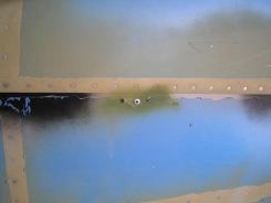 Exterior view
of static port
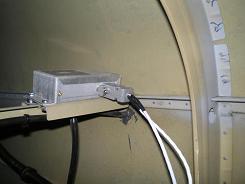 Interior view of static port
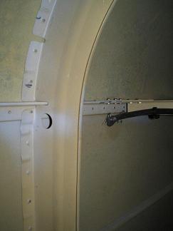 Interior view of
static port Interior view of
static portI split the lines behind
the
instrument panel to feed the various inputs. I used the
plastic T’s to connect the each line to several instruments.
The AOA only connects to the Dynon, but the other two provide
input to multiple instruments.
|
 I
ran the pitot (and
because I have the Dynon, I also ran
AOA) as shown in the Vans plans. I did
have to drill an extra hole in each wing rib for the AOA
line. I used a rubber grommet in
each hole to protect
the neoprene. I
pushed the neoprene line
onto the metal ends of the pitot tube and secured them
with worm
clamps. I wanted to
be able to pull the
wings off without having to cut the hose, so I used straight connectors
at the
wing root. If I ever pull the wings, it will be important to
mark the two lines. I would not want to reconnect them
backwards -- it could lead to some really strange airspeed and AOA
readings.